LEARN ALL ABOUT OUR OPTICLIMATE AND DIMLUX PRODUCTS
DIMLUX LED
DIMLUX MKII
DIMLUX PRO
DIMLUX EXPERT
OPTICLIMATE
WATER-COOLED
OPTICLIMATE
AIR-COOLED
DIMLUX XTREME SERIES LED
Getting started
LED safety & General Care
LED Quick Start Guide
Terminology
Documentation
LED Specifications
Whitepaper
Manuals
How to
First Time Use
Set LED Fixture Settings
Use Dimlux Plant Temperature Camera
Connect the Maxi Controller
Use Sensors
Alarms, Updates & Backup
Chaining LED Fixtures
Manuals
DIMLUX EXPERT SERIES MKII
Getting started
Unboxing
UNBOXING Your Dimlux fixture box will contain the following items:
1x DimLux fixture + bulb
1x Interlink cable (315&600W=2.0m 630&1000W=2.5m)
1x Power cord
2x Eye bolt and nut (M6)
1x Instruction manual
Extra Interlink cables are available in different sizes 0.6 m (24 in.) 1,0 m (40 in.) 1.5 m (60 in.) 2,0 m (80 in.) 2,5 m (100 in.) 3,5 m (140 in.) 5,0 m (200 in.) 10,0 m (400 in.)
4 Digit display
Status and alarms will be displayed on this display. The DimLux Expert Series MKII ballast achieves the highest possible light output due to the overdrive technology (boost) in combination with the 400V control. This makes it possible to get 15% extra growlight form your tubes.
Single push button for setting the power output:
Dimlux Expert 1000W in steps of 500, 600, 700, 800, 900, 1000, 1100 ,1200W
Dimlux Expert 600W in steps of 320, 390, 460, 530, 600, 645, 720W
Suitable Bulbs
Dimlux Expert 600 watt EL UHF
- Philips Greenpower 600W EL UHF (400volt)
Dimlux Expert 1000 watt EL UHF
- Philips 1000W Philips Master Greenpower EL DE
- Dimlux 1000W PRO
- Dimlux 1000W MKII Ultra
- Horturion MH 1000 DE EL 5.5K
- DimLux HPS1000 PRO DE 2K
- Dimlux Xtreme Output California Spec HPS 400V 1000/1250W DE
Please ensure that the bulb has been burning for at least 5 minutes before turning off the power. Short ON/OFF cycles can shorten the lifespan of the installed 315W bulb.
Closed & Vertical Ballast
Closed ballast design, for better protection of the electronics.
Unparalleled and highly efficient ballast driver : 97% efficient, 30% less losses, lighter and 30% more compact than the old Dimlux Expert Series
Easy Removable Ultra Optics Reflector
Standard equipped with the Ultra Optics Hybrid 98 reflector. This reflector has the highest reflector efficiency in the market with 98% total efficiency, achieved through Miro 98 (99.99% silver) and the SBCS (Single Bounce Clear Sight) principle.
Easy to replace with the Ultra Optics Wide 98 reflector or Ultra Optics Deep 98 reflector. Both reflectors have a 98% efficiency just like the Ultra Optics Hybrid 98.
How to
Error codes
If there is an error message, it will scroll across the display.
- LVP error low voltage protection = Input voltage too low
- HTP error high temperature protection = The ballast is over heated
- OCP error open contact = Open contact, or lamp is defective
- SHORT error short circuit = Short circuit in the lamp circuit, or lamp is defective
- EOL error end of live bulb = Lamp surpassed it’s service life. Maximum power connot be attained anymore.*
If there is a (mains) power failure (but the fixture is connected to other fixtures, “psu fail” will scroll across the display. If there is an internal error in the electronics that drive the lamp, then “hid fail” will scroll across the display.
* When EOL appears, then it’s possible that the lamp will still work fine at lower powers.
Installation
Documentation
MKII Specifications
Manuals
DIMLUX PRO SERIES
Getting started
4 Digit display
Display with a dim switch and boost
Status and alarms will be displayed on this display. The Dimlux Pro Series can be remote controlled and controlled with the dim switch and with a 1000W bulb and in boost it can go up to 1150W.
Closed & Vertical Ballast
The Dimlux Pro Series has a closed ballast instead of an open ballast. This to prevent moisture getting into the ballast. The ballast is mounted vertically to decrease the amount of light which is intercepted by the fixture. The Dimlux Pro Series has the least light interception during a full day light cycle.
Smar Ballast
The ballast is software upgradable and ready for the new digital controller platform
GEO MEMBRANE
This to equalize the pressure inside and outside the ballast, this is to prevent moisture getting into the ballast when cooling off.
Easy Removable Ultra Optics Reflector
How to
Error codes
Display indication on Dimlux Pro (Analog version only)
Flashing = Ignition Running No action needed.
1x = Ignition Failure (Timeout) Place lamp or replace defected lamp.
2x = Ignition Interval No Action needed.
3x = Undervoltage Correct mains voltage within specified limits.
4x = Overheat Reduce ambient temperature.
5x = Lamp End-of-Life Change lamp.
6x = Overvoltage Correct mains voltage within specified limits.
Display indication on Dimlux Pro (Digital versions only)
If there is an error message, it will scroll across the display.
LVP error low voltage protection = Input voltage too low
HTP error high temperature protection = The ballast is over heated
OCP error open contact = Open contact, or lamp is defective
SHORT error short circuit = Short circuit in the lamp circuit, or lamp is defective
EOL error end of live bulb = Lamp surpassed it’s service life. Maximum power connot be attained anymore.*
If there is a (mains) power failure (but the fixture is connected to other fixtures, “psu fail” will scroll across the display. If there is an internal error in the electronics that drive the lamp, then “hid fail” will scroll across the display.
* When EOL appears, then it’s possible that the lamp will still work fine at lower powers.
Documentation
PRO Specification
DIMLUX EXPERT SERIES
Getting started
Bulb Replacement
The Dimlux 315W CDM bulbs have a bayonet connector. When installing a new bulb, ensure that the two pins, one large and one small, are lined up with the holes in the socket, then push and turn to lock the bulb in place. The 1000W DE bulb has 2 wire clamps. The 600W Dimlux fixtures use 600W bulbs with E40 ‘screw in’ sockets. Simply unscrew the old bulb and screw in the new one, making sure that it is screwed in tight and straight to avoid any performance issues.
Closed & Vertical Ballast
Closed ballast design, for better protection of the electronics.
Unparalleled and highly efficient ballast driver : 97% efficient, 30% less losses, lighter and 30% more compact than the old Dimlux Expert Series
Easy Removable Ultra Optics Reflector
Standard equipped with the Ultra Optics Hybrid 98 reflector. This reflector has the highest reflector efficiency in the market with 98% total efficiency, achieved through Miro 98 (99.99% silver) and the SBCS (Single Bounce Clear Sight) principle.
Easy to replace with the Ultra Optics Wide 98 reflector or Ultra Optics Deep 98 reflector. Both reflectors have a 98% efficiency just like the Ultra Optics Hybrid 98.
How to
Error codes
Each Dimlux fixture has its own self diagnosis system. A display on the side of each unit shows error and status information.
Status
F-Flash = Soft off – The ballast is off because the dim button is on soft-off.
F-on = On-DB – The ballast is on, no maxi controller detected.
A-Flash = Off remote – The ballast is off by maxi controller. A-on = on remote The ballast is on by maxi controller.
1-strobo = Igniting – The ballast is igniting the lamp.
Error
2-On = HVP – Error. The input voltage is too high.
3-On = LVP – Error. The input voltage is too low.
4-On = HTP – Error. The ballast is too hot.
5-On = Open – Error. Open contact or lamp failure.
6-On = Short Error. Short in lamp circuit or lamp failure. 7-On = EOL Error. Replace lamp.
Documentation
Expert Specifications
Manuals
OPTICLIMATE WATER-COOLED
Getting started
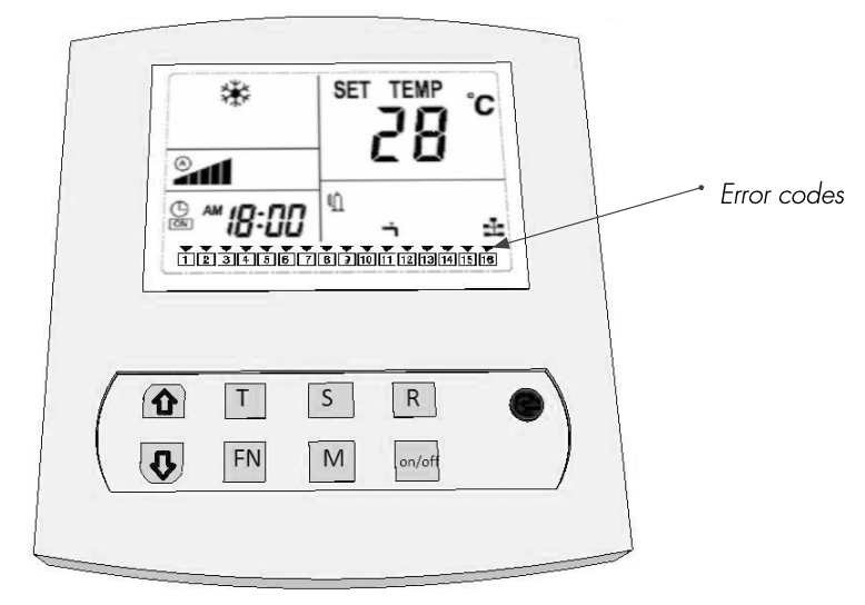
Remote control
↓ = Temp down / scroll
T = Press and release to set the time / press and hold to set the timer
FN = Fan speed
S = Press and release to read Sensors / press and hold to bring up the Menu
R = Press and release to confirm / press and hold to delete error codes M = Press and release to switch between day and night mode. Press and hold to turn automatic light cell mode on/off.
On/Off = Turn unit on/off or confirm menu option.
Temperature sensors
C:01= Temperature cooling block
C:02= Temperature drain water
C:03= Temperature supplied water (with dual room configuration, this will be the temperature sensor for room 2)
C:04= Intake air temperature
C:05= Temperature outlet air
C:06= Temperature of low-pressure refrigerant for compressor
C:07= Water leakage sensor
Power cables and circuit breakers
Six different OptiClimate models are available. For your safety and the safety of the OptiClimate, the following specifications should be observed when connecting the power supply: use the circuit breakers (MCB) and cable thickness specified.
| Model | |||
| 2000 | PRO3 & PRO4 | 1 phase D16 MCB | 2.5mm2 cable |
| 2000 | PRO3 & PRO4 | 3 phase D16 MCB | 2.5mm2 cable |
| 3500 | PRO3 & PRO4 | 1 phase D16 MCB | 2.5mm2 cable |
| 3500 | PRO3 & PRO4 | 3 phase D10 MCB | 2.5mm2 cable |
| 6000 | PRO3 & PRO4 | 1 phase D25 MCB | 4.0mm2 cable |
| 6000 | PRO3 & PRO4 | 3 phase D16 MCB | 2.5mm2 cable |
| 10000 | PRO3 & PRO4 | 1 phase D35 MCB | 4.0mm2 cable |
| 10000 | PRO3 & PRO4 | 3 phase D20 MCB | 2.5mm2 cable |
| 15000 | PRO3 & PRO4 Inverter | 1 phase D50 MCB | 6.0mm2 cable |
| 15000 | PRO3 & PRO4 Inverter | 3 phase D35 MCB | 4.0mm2 cable |
| 15000 | PRO3 & PRO4 | 3 phase D25 MCB | 4.0mm2 cable |
How to
Error codes
Error 01 = Usually means that the phases are crossed (reversal).
Error 02 = Condensate does not drain.
Error 03 = Drain water temperature is higher than 57°C.
Error 04 = Ambient temperature is too low.
Error 05 = Ambient temperature sensor is not connected or is defective.
Error 06 = Cooling block temperature sensor is not connected or is defective.
Error 07 = Return cooling temperature sensor is not connected or is defective.
Error 08 = Water leakage safeguard is active. There is a water leak.
Error 09 = The compressor consumes too much current.
Error 10 = The temperature of the cooling block is too low.
Error 11 = Poor cooling. There is no proper cooling.
Error 12 = High pressure protection.
Error 13 = Low pressure protection.
Error 14 = Current interruption alarm. The unit is deprived of current.
Error 15 = High ambient temperature safeguard is active.
Error 16 = Water leakage safeguard is active. There is a leak.
Error 18 = Outlet air sensor faulty or not connected.
Error 19 = Temperature low pressure sensor faulty or not connected.
Error codes video explenation
Documentation
Manuals
OPTICLIMATE AIR-COOLED
Getting started
Remote control
↓ = Temp down / scroll
T = Press and release to set the time / press and hold to set the timer
FN = Fan speed
S = Press and release to read Sensors / press and hold to bring up the Menu
R = Press and release to confirm / press and hold to delete error codes M = Press and release to switch between day and night mode. Press and hold to turn automatic light cell mode on/off.
On/Off = Turn unit on/off or confirm menu option.
Temperature sensors
C:01= Temperature cooling block
C:02= Temperature of refrigerant outdoor unit (liquid / return)
C:03= Temperature supplied water (with dual room configuration, this will be the temperature sensor for room 2)
C:04= Intake air temperature
C:05= Temperature outlet air
C:06= Temperature of low-pressure refrigerant for compressor
C:07= Water leakage sensor
Power cables and circuit breakers
Six different OptiClimate models are available. For your safety and the safety of the OptiClimate, the following specifications should be observed when connecting the power supply: use the circuit breakers (MCB) and cable thickness specified.
| Model | |||
| 2000 | PRO3 & PRO4 | 1 phase D16 MCB | 2.5mm2 cable |
| 2000 | PRO3 & PRO4 | 3 phase D16 MCB | 2.5mm2 cable |
| 3500 | PRO3 & PRO4 | 1 phase D16 MCB | 2.5mm2 cable |
| 3500 | PRO3 & PRO4 | 3 phase D10 MCB | 2.5mm2 cable |
| 6000 | PRO3 & PRO4 | 1 phase D25 MCB | 4.0mm2 cable |
| 6000 | PRO3 & PRO4 | 3 phase D16 MCB | 2.5mm2 cable |
| 10000 | PRO3 & PRO4 | 1 phase D35 MCB | 4.0mm2 cable |
| 10000 | PRO3 & PRO4 | 3 phase D20 MCB | 2.5mm2 cable |
| 15000 | PRO3 & PRO4 Inverter | 1 phase D50 MCB | 6.0mm2 cable |
| 15000 | PRO3 & PRO4 Inverter | 3 phase D35 MCB | 4.0mm2 cable |
| 15000 | PRO3 & PRO4 | 3 phase D25 MCB | 4.0mm2 cable |
How to
Error codes
Error 01 = Usually means that the phases are crossed (reversal).
Error 02 = Condensate does not drain.
Error 03 = Drain water temperature is higher than 57°C.
Error 04 = Ambient temperature is too low.
Error 05 = Ambient temperature sensor is not connected or is defective.
Error 06 = Cooling block temperature sensor is not connected or is defective.
Error 07 = Return cooling temperature sensor is not connected or is defective.
Error 08 = Water leakage safeguard is active. There is a water leak.
Error 09 = The compressor consumes too much current.
Error 10 = The temperature of the cooling block is too low.
Error 11 = Poor cooling. There is no proper cooling.
Error 12 = High pressure protection.
Error 13 = Low pressure protection.
Error 14 = Current interruption alarm. The unit is deprived of current.
Error 15 = High ambient temperature safeguard is active.
Error 16 = Water leakage safeguard is active. There is a leak.
Error 18 = Outlet air sensor faulty or not connected.
Error 19 = Temperature low pressure sensor faulty or not connected.